Assembly
Step-by-step v1 assembly with mechanical, orientation, electrical, and first-power checkpoints.
ESPFlight Docs · v1 • Validated v1 documentation path
# Prepare the build
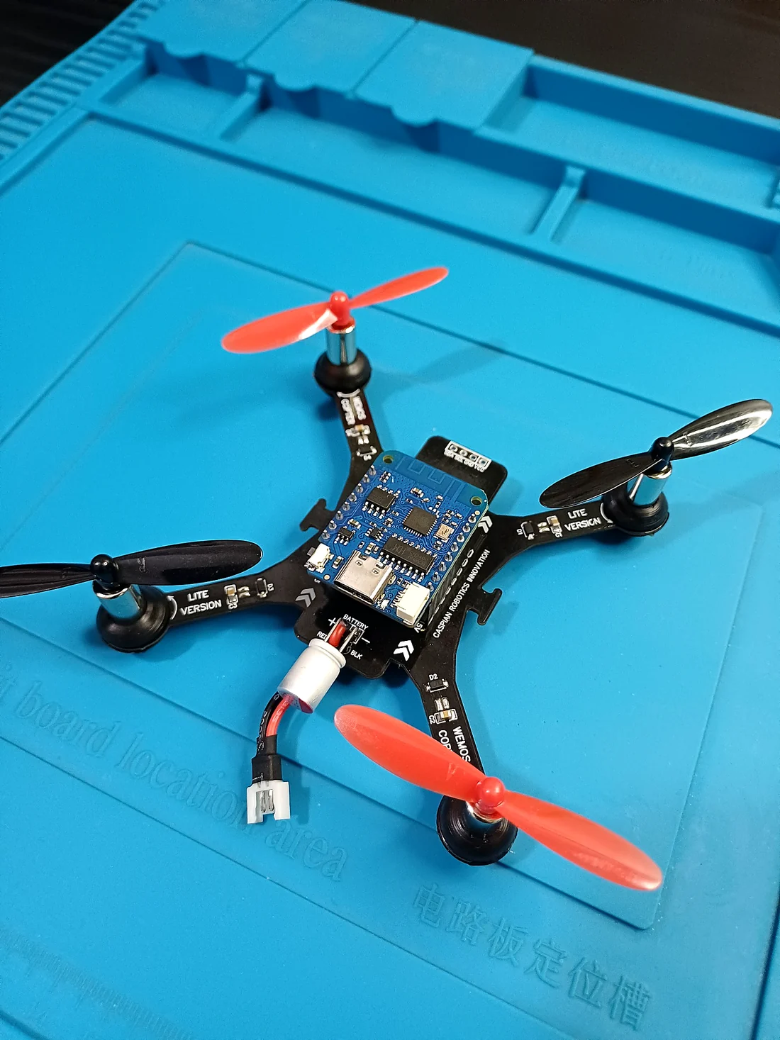
Confirm Hardware Reference v1.0 or clearly document your modified revision.
Match the schematic, BOM, board files, and orientation references before placing parts.
Keep the battery disconnected and propellers off throughout assembly and first power-up.
# Assembly sequence
- Inspect the bare PCB. Check board outline, pads, vias, obvious fabrication damage, and unintended solder bridges before adding modules.
- Install low-profile parts first. Work from the board reference and keep polarized parts or connectors in the documented orientation.
- Fit headers and modules squarely. Dry-fit the ESP8266 and sensor modules before soldering so their headers are parallel and do not mechanically stress the PCB.
- Verify IMU orientation. The physical sensor orientation must match the firmware/wiring reference; do not assume a rotated module will behave correctly without corresponding software changes.
- Connect motor outputs deliberately. Keep M1–M4 identity clear and route motor wiring so it cannot contact propellers or pull on solder joints.
- Finish power and peripheral wiring. Recheck battery polarity, supply/ground continuity, LED/buzzer connections, and any optional sensor connections against the schematic.
- Secure the build mechanically. Prevent modules, wires, and the battery from moving into the propeller path or transferring force into small solder joints.
# Electrical inspection before power
Measure for an unexpected short between the main supply and ground.
Verify battery polarity and the intended supply path.
Inspect every solder joint under good light and correct bridges, cold joints, or loose headers.
Confirm module orientation, I²C wiring, motor channel identity, and connector alignment.
FIRST POWER-UP
Keep propellers removed. If available, use a current-limited bench supply or another controlled power method appropriate to your build and stop immediately if a component heats unexpectedly.
# Assembly checkpoint
After the board passes visual and electrical inspection, continue to Wiring & Orientation and then Hardware Verification . Do not install propellers or move directly to flight testing.